

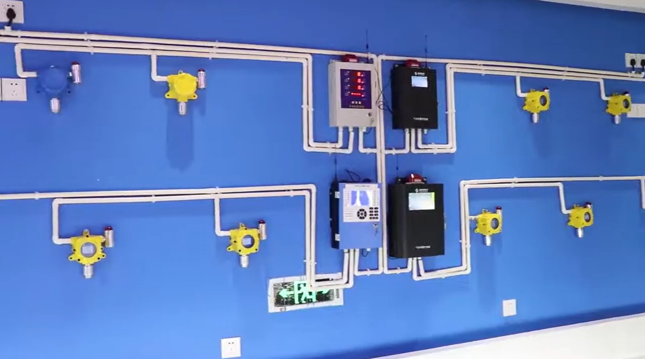
On a floor plan, two points separated by a partition can look close enough to share a sensor. Air may take a much longer route between them. The height and spacing of a fixed gas detector depend on where gas could escape, how it could travel under credible operating conditions, and where an alarm would give people time to respond.
Placement therefore begins with a release and airflow survey. The resulting layout assigns a purpose to each sensing point and records the conditions that could change its usefulness. A layout review can then address coverage, while commissioning checks whether the installed equipment carries a detected event through to the intended alarm or response.
Map the Release Before Marking the Wall
The release survey begins with the equipment that contains the gas. Valves, flanges, compressor connections, and tank fittings are useful landmarks because each can release gas from a different height or direction. Marking them alongside doors, partitions, extraction points, and occupied areas makes it possible to trace where a release could go and who could encounter it.
Ventilation gives that map a direction. A fan may pull air across a room toward an extract point, while a screen around a machine may leave a pocket outside that route. Changes in door position or operating mode can alter the path, so the survey needs to reflect how the room is used during the shift.
The map also clarifies what an individual fixed gas detector is intended to do. One point may monitor a likely equipment leak, while another may monitor a route along which gas could reach an occupied area. Those objectives may lead to different locations even when the target gas is the same.
Choose Height Along the Expected Gas Path
Relative density supplies an initial hypothesis for the elevation survey. Methane tends to rise in still air, while carbon dioxide can accumulate at lower levels. A warm discharge, a pressurized jet, or forced airflow can change the initial path, and a beam or equipment platform can affect where a rising plume collects.
Mounting height has to account for both the expected route and the orientation specified by the gas detector manufacturer. With the Bosean K-G60 wall-mount arrangement, the sensing head faces downward. The drawing therefore needs to show where the sensing head sits relative to the expected air path and whether nearby structures could obstruct it.
Practical access can decide between points that serve the same purpose. A location next to a ceiling feature or above a recessed floor can look sensible on a sectional drawing yet leave too little room for inspection and testing. Showing the access route alongside the elevation makes these issues visible before installation.
Relate Spacing to Separate Air Spaces
Routes on the survey give meaning to the proposed spacing. A fixed gas detector senses gas that reaches its sensing point. Distance from a potential leak is one part of that path, along with barriers, ventilation, and any rise or drop between the source and the point where the detector samples the air.
A pump on one side of a divider and a service pit on the other illustrate the problem. Even if both are close to the same wall, the divider can redirect airflow and the pit can collect gas below the surrounding floor. Each space deserves a separate coverage assessment and may call for its own sensing point.
Spacing also depends on how much gas may reach a sensor after mixing with the surrounding air. Downstream of a strong supply of fresh air, gas from a small leak may become more dilute. A coverage review therefore considers both the direction in which gas travels and how the expected airflow could affect the concentration at each sensing point.
Equipment fit can influence that decision. At a proposed wall location for a Bosean K-G60, the bracket and housing need room as well as the sensing head. Comparing the actual configuration with the installation details from the gas detector manufacturer keeps the survey tied to a sensing location that can be mounted and maintained as intended.
Verify Coverage and the Signal Path Separately
An installed sensor can respond correctly during a functional test even if air rarely moves toward it from a proposed leak point. Checking placement assumptions against the installed equipment can reveal relocated partitions or ventilation outlets. The handover record identifies which release scenarios each point is intended to address and which changes would warrant another review.
A controlled functional check serves a different purpose. Following the procedure specified by the gas detector manufacturer, the test can establish that the sensor responds and that the control system shows the correct channel. For an installation using a Bosean K-G60 with a 4–20 mA signal, commissioning can also trace the intended alarm and connected response through the receiving equipment.
Across the partition from the opening example, a point earns its place when a credible release can reach it at the selected height. The handover record ties that path to the proposed spacing and to the response verified during commissioning. A future change to the divider or ventilation can then be assessed against the reason each point was placed where it is.
SEO Title: Fixed Gas Detector Placement: Height and Spacing
Meta Description: Explore how likely release points, airflow and partitions influence fixed gas detector height and spacing, and what to verify during commissioning.

