

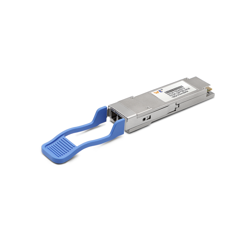
Heat is an often-overlooked factor in optical network stability. As data rates increase and equipment becomes more densely packed, transceiver modules must operate within thermal limits while maintaining reliable signal transmission. An SFP fiber optic transceiver converts electrical signals into optical signals and back again, but its performance depends partly on how effectively heat generated by internal components moves away from sensitive circuitry. Understanding this relationship helps network engineers plan installations, diagnose intermittent faults, and extend equipment service life.
Understanding Where Transceiver Heat Comes From
Electrical power consumed by a transceiver does not all become useful optical output. Lasers, driver circuits, signal-processing components, and other electronic elements generate heat during operation. Higher transmission rates and more demanding signal-processing requirements can increase power consumption, although actual thermal behavior varies by design and operating conditions.
Temperature affects several aspects of optical performance. Laser characteristics can shift as junction temperature changes, influencing wavelength stability and optical output. Receiver sensitivity and electronic circuit behavior may also vary with temperature, potentially reducing the available operating margin if the module approaches its specified limits.
Ambient conditions add another layer of complexity. A module installed inside a crowded switch chassis may experience warmer surrounding air than an identical unit operating in a ventilated laboratory. Nearby power supplies, adjacent transceivers, restricted airflow, and elevated room temperatures can all contribute to a higher operating temperature.
How Airflow and Installation Design Affect Heat Dissipation
The path through which heat escapes matters as much as the amount generated. Transceiver modules typically transfer heat through their internal structures and surrounding air, while the host device provides additional thermal management through chassis design and cooling systems. Blocked vents or poorly arranged equipment can restrict heat removal even when each component operates within its individual power rating.
Rack density deserves particular attention in data centers and telecommunications facilities. Installing multiple high-speed optical modules in neighboring ports increases the local heat load, especially when switches operate continuously under heavy traffic. Equipment designers may account for these conditions through airflow channels, heat sinks, and fan-control strategies, but actual performance depends on the complete system configuration.
Network planners should also consider the host device’s airflow direction and cooling specifications before installation. Front-to-back and back-to-front cooling arrangements are not interchangeable in every rack layout. Keeping blanking panels in unused rack spaces, maintaining appropriate clearance, and cleaning air filters according to the equipment manufacturer’s guidance can help preserve the intended cooling path.
Monitoring Temperature and Diagnosing Thermal Problems
Temperature monitoring can help distinguish thermal issues from fiber faults, configuration errors, or failing hardware. Where digital diagnostic monitoring is supported, compatible modules may report internal temperature, supply voltage, laser bias current, transmit optical power, and received optical power. Reviewing these readings alongside switch logs provides a more useful picture than relying on a single alarm.
Symptoms of excessive heat are not always obvious. A network link might remain active while experiencing intermittent errors, unexpected optical power changes, or occasional disconnections during periods of high ambient temperature. Correlating these events with traffic load, chassis temperature, fan speed, and environmental conditions can help technicians identify whether heat is a contributing factor.
Maintenance teams should interpret measurements against the specific module’s datasheet rather than applying a universal temperature threshold. Operating limits, alarm settings, diagnostic accuracy, and available monitoring functions differ among models. A temperature reading within the module’s rated range also does not automatically rule out inadequate cooling elsewhere in the host system.
Selecting Modules With Thermal Requirements in Mind
Thermal assessment should form part of the wider compatibility review, alongside transmission distance, wavelength, fiber type, data rate, and host-device support. Power consumption is particularly relevant in high-density installations because the cumulative heat generated by many modules can affect chassis cooling requirements. Evaluating the full system is more informative than comparing individual modules in isolation.
For deployments requiring different transmission speeds and optical configurations, WINTOP’s product portfolio includes 155M, 1.25G, 10G, 25G, 40G, and 100G transceiver options, according to its company-provided information. The range covers different wavelengths, transmission distances, and fiber types. Buyers should review the relevant datasheets and test documentation to verify each module’s operating temperature range and environmental suitability. Specific power consumption, operating-temperature limits, and diagnostic capabilities should be confirmed from the relevant product datasheet before a module is selected.
Procurement and engineering teams can reduce avoidable thermal risks by requesting model-specific specifications, checking compatibility with the host’s cooling design, and testing representative configurations under realistic workloads. For critical links, recording baseline temperatures and optical measurements after installation makes later comparisons more meaningful. These practices help teams identify gradual changes before they develop into persistent network problems.
Conclusion
Thermal management is a system-level responsibility involving optical components, host equipment, airflow, and the surrounding environment. Careful installation, meaningful diagnostic monitoring, and datasheet-based selection help maintain stable optical links as network capacity grows. With in-house research and development and factory production, WINTOP provides optical transceiver options for a range of networking applications. Visit the official WINTOP website to review its product portfolio and obtain the technical specifications relevant to a planned deployment.

